Plain Control Knobs
Provide compact direct shaft adjustment where no scale is needed. Bore, shaft flat, fastening method, rotation and finger clearance control the interface.
Manual adjustment and control hardware
A useful selection starts with what the operator must turn or adjust, then controls the required effort, movement, feedback, shaft connection and full operating envelope.

Direct answer
Choose a control knob when compact direct shaft adjustment suits the required travel, effort and feedback; evaluate a handwheel when a larger operating diameter or repeated rotation is needed. Define shaft torque, movement, direction, operator conditions, clearance and the shaft-and-hub interface first. Then verify the exact candidate drawing, retention, materials and machine-level risk controls.
TW RFQ reviews standard-part and drawing-based knob or handwheel requests against the stated machine function and interface. A sourcing review does not establish torque capacity, ergonomics, safety compliance, availability or a quotation for an unnamed part.
TW RFQ synthesized this sequence from machinery-safety sources and original manufacturer examples. The sources establish narrower actuator principles or product configurations; they do not define universal torque limits, certify a candidate or approve an installed machine.
Product families
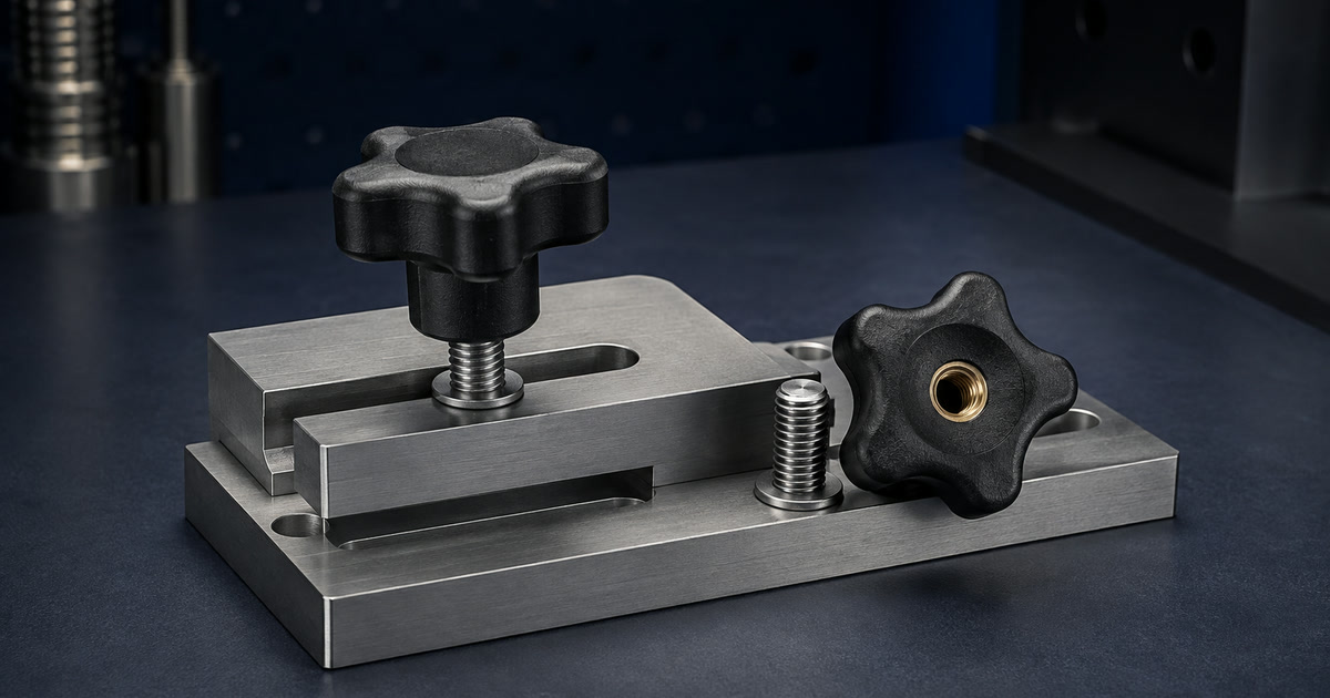
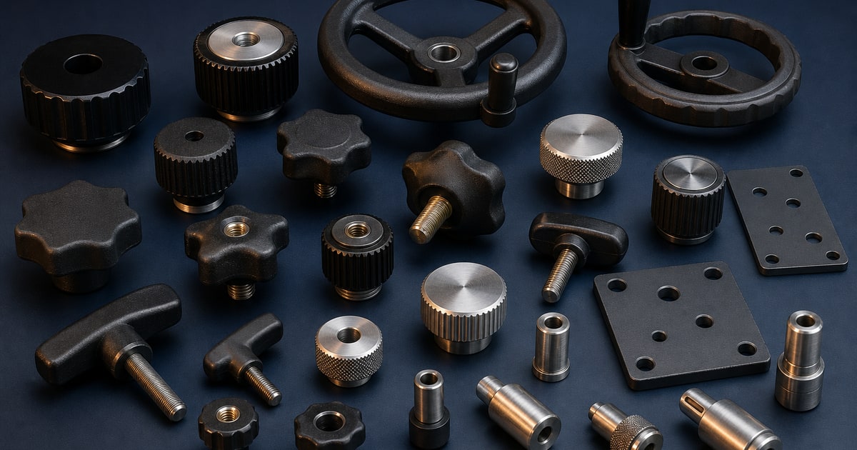
These families serve different adjustment and clamping tasks. Begin with the required motion and operator interaction instead of choosing by shape alone.
Provide compact direct shaft adjustment where no scale is needed. Bore, shaft flat, fastening method, rotation and finger clearance control the interface.
Apply hand torque through an internal thread or projecting stud. Thread, engagement, seating surface and clamp load remain part-specific.
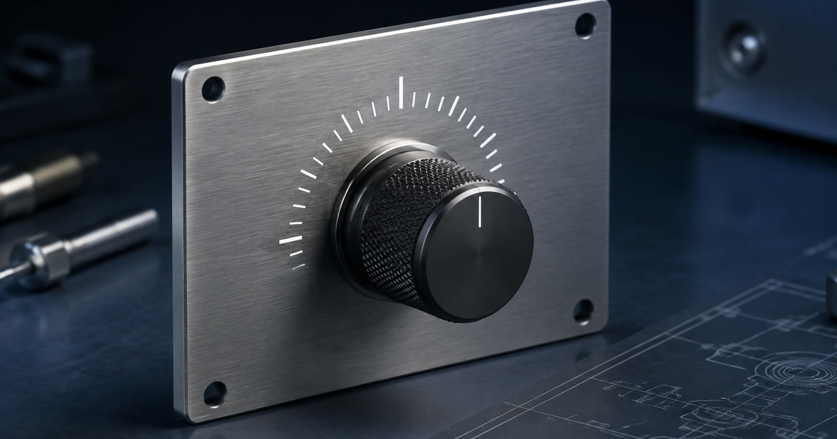
Add visible setting reference. Zero, scale direction, units, pointer relationship and whether indication is informational or controlled must be defined.
Provide a larger operating diameter with a closed rim. Hub connection, sweep, mounting access and nearby clearances still govern suitability.
Provide a larger rim with open access. Spoke geometry, fixed-member clearance and rotating nip-point risk require installed-machine review.
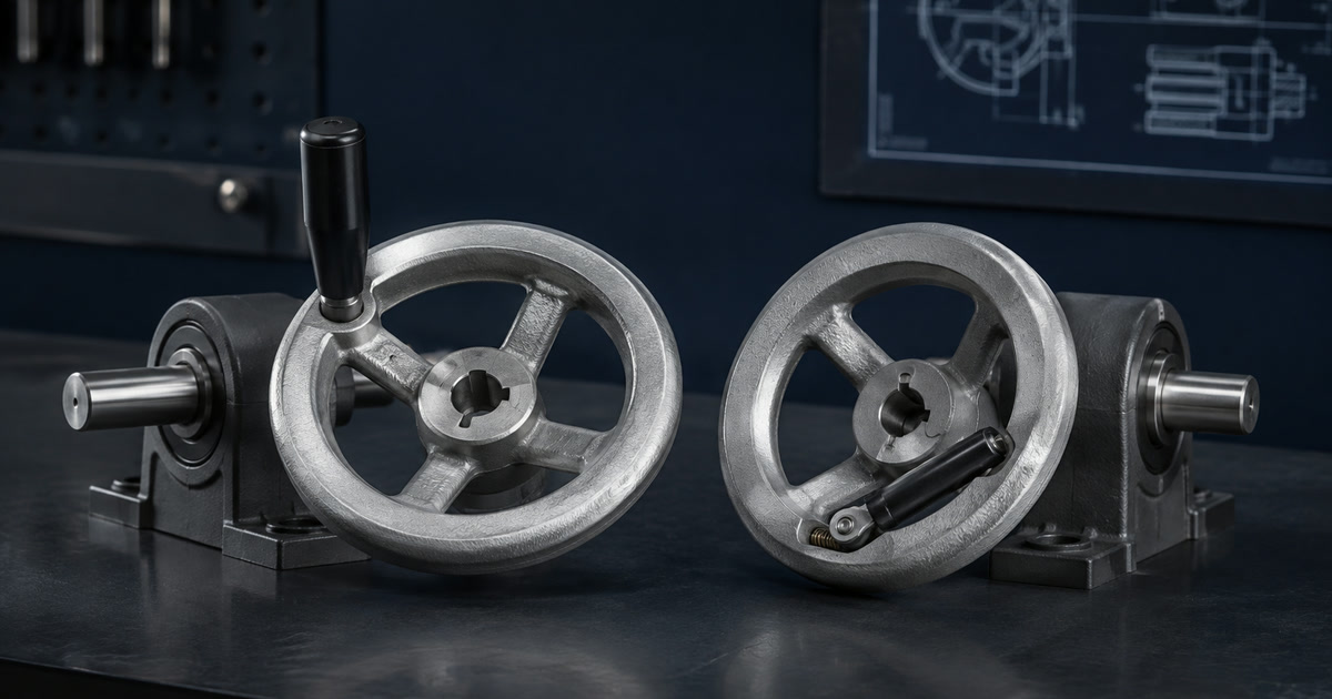
Support repeated cranking with fixed, revolving or retractable handles. Define offset, projection, return behavior and the complete operating envelope.
Selection factors
The candidate drawing must connect the human input to the real shaft, hub, retention and machine motion. A reference photo alone cannot do that.
| Factor | What to specify |
|---|---|
| Control task and machine state | State what is adjusted, total travel or turns, direction, resolution, back-drive behavior and whether adjustment occurs while powered. |
| Operating effort | Provide shaft torque or force profile, starting and running conditions, use frequency, posture, glove use and permitted operating force. |
| Shaft and hub interface | Dimension the bore, shaft tolerance, flat, keyway, square, spline or cross hole, engagement length and torque-transfer feature. |
| Axial retention | Define the set screw, clamp, pin, washer, nut or other retention method plus assembly access and allowable shaft marking. |
| Feedback and indication | Specify zero, pointer, graduations, detents, friction, stops, backlash and vibration-induced movement only where required. |
| Environment and risk controls | State materials, finish, temperature and chemical exposure, then assess projection, entanglement, pinch and unexpected-motion risks on the machine. |
Option comparison
Evaluate a control knob for compact direct adjustment when the required effort and travel fit a small diameter. Evaluate a handwheel when a larger diameter, repeated rotation or a cranking handle better suits the task. In both cases, calculated effort, shaft connection, clearance, feedback and installed-machine risk control the decision.
| Decision factor | Control knob | Handwheel |
|---|---|---|
| Typical motion | Compact direct angular or limited-turn adjustment. | Larger-diameter adjustment, often through repeated rotation. |
| Primary interface | Bore, flat or collet, set screw and pointer relationship. | Hub bore, keyway or clamp, axial retention and optional handle. |
| Operator input | Finger or hand grip around the knob body. | Rim input or cranking through a fixed, revolving or retractable handle. |
| Installed review | Finger clearance, indication, stops, effort and adjacent controls. | Full sweep, spoke and handle projection, effort, pinch points and unexpected rotation. |
Copy into your request
Replace every bracketed field. Keep unknown items visible instead of silently omitting them.
Function: [what the operator adjusts and machine state]
Movement and torque: [travel/turns, direction, starting/running/reversing torque]
Operator and use frequency: [posture, gloves, cycles and acceptable effort]
Shaft and hub interface: [bore, tolerance, flat/keyway/spline, engagement]
Axial retention and feedback: [fastener, pointer, scale, detent, stops, backlash]
Rotation envelope, environment and safety controls: [clearance, projection, exposure, guarding]
Supply route, quantity and evidence: [standard/modified/custom, prototype, order volume, sample checks]Practical answer
Show the shaft diameter and tolerance, engagement length, flat, keyway, square, spline or cross hole, hub length, axial position and retention method. State the required transmitted and reversing torque separately. Identify assembly access, allowable shaft marking and whether the knob, handwheel or machine provides travel stops and axial restraint.
Application decision
Use the machine state, motion and required human input to narrow the family, then verify the exact interface and risk controls.
| Operating or supply decision | RFQ direction |
|---|---|
| Compact unmarked adjustment | Evaluate a plain control knob with the shaft flat or bore, fastening method and finger clearance defined. |
| Limited-angle setting | Define travel, zero, stops, detent positions and whether the component or machine carries stop loads. |
| Visible position reference | Define pointer, graduations, units, direction and whether the indication is informational or an acceptance feature. |
| Repeated manual rotation | Evaluate a handwheel diameter and optional handle from required effort, use frequency and the full rotation envelope. |
| Powered or back-driven shaft | Review unexpected rotation, projection, guarding and access as part of the installed machine risk assessment. |
| Standard catalog part | Identify the exact manufacturer, part number, revision, shaft interface and evidence; do not assume all variants share the same data. |
| Modified-standard part | Identify the base part and every controlled bore, keyway, thread, set-screw, scale or marking modification, including who performs and inspects it. |
| Custom part | Supply a controlled drawing, material and finish requirements, tooling ownership, sample approval, forecast quantities and change-notification requirements. |
Installed interface
The RFQ should connect operator input, component geometry and shaft retention to one controlled assembly.
What is adjusted, total travel or turns, direction, resolution, back-drive and machine state.
Starting, running, reversing or jam torque plus acceptable operator force and use frequency.
Bore, tolerance, flat, keyway, square, spline, pin, engagement length and torque transfer.
Axial restraint, fasteners, zero, pointer, graduations, detent, friction and backlash.
Full sweep, projection, clearances, materials, finish, chemicals, temperature and cleaning.
Typical use
The same hardware family can behave differently across enclosure types. Include the installed context, not only the component name.
Manual set-point or selector interfaces requiring a defined shaft connection, indication and operator clearance.
Lead screws, stops, tensioners and positioning mechanisms with a calculated effort and controlled rotation envelope.
Hand-operated threaded clamping points where thread engagement, seating and repeated use must be specified.
Service or emergency-use interfaces that need a defined machine state, access procedure and risk review.
Technical boundaries
Use measurable requirements and identify the requested test basis. Product-family names alone do not establish performance or certification.
Technical reference basis
This category guide supports RFQ preparation. It does not replace an exact supplier drawing, model data, test report, applicable standard or responsible engineering approval.
Sources last checked: .
Original manufacturer family overview illustrating that handwheels use different materials, forms and shaft connections. It does not establish universal load capacity.
Part-family example of a limited-angle control knob with restriction and detent options; it supports only that documented configuration.
Part-family example of a retractable operating handle. The feature is not machine-level safety approval.
Official scope for manual-actuator location, direction, arrangement and the relationship between action and machine effect.
Official current-edition scope for machinery hazard identification, risk estimation, evaluation and risk reduction. ISO lists the standard as under revision, so confirm the buyer-required edition.
Official machine-guarding guidance identifying rotating motion and nip-point hazards, including spoked handwheels near fixed parts.
Buyer questions
Use these answers to prepare a more specific sourcing request.
A knob is commonly evaluated for compact direct shaft adjustment. A handwheel provides a larger operating diameter and may support repeated rotation or a separate cranking handle. Required effort, travel, clearance and the exact interface determine the choice.
Start with required shaft torque, a buyer-approved tangential operating-force limit, use frequency, posture, glove use and available sweep. In consistent units, required shaft torque divided by that force gives a first-pass effective radius. Then account for grip geometry, starting, reversing and jam loads, hub connection and machine-level risk before verifying the exact candidate on a representative sample.
Select the connection from transmitted and reversing torque, shaft geometry, axial retention, assembly access, serviceability and allowable shaft marking. The candidate drawing must define dimensions and tolerances.
Not by itself. Review rotating projections, pinch points, unexpected powered movement, guarding and the complete use case. A product feature is not a substitute for machine-level risk assessment and verification.
Possibly, but do not assume every series permits every change. Identify the exact base part and controlled modification drawing, quantities, marking authorization, tooling or setup cost, who performs and inspects the work, and the sample evidence needed before release.
Private sourcing review
Send the interface and commercial requirements for a focused Taiwan sourcing review.