L, Z & U Brackets
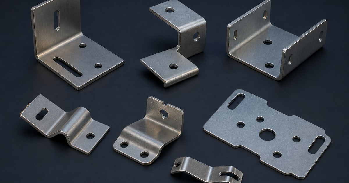
Formed supports and mounting interfaces defined by sheet thickness, bend direction, inside radius and hole locations.
Drawing-based metal parts
Custom metal stampings and formed enclosure parts turn a design into manufacturable bends, holes, inserts and finishes. A useful RFQ defines the part geometry, material condition, tolerances and inspection basis.
Direct answer
A quotable custom enclosure bracket needs a controlled drawing revision, units, material and thickness, datums and tolerances, bends and features, finish, inspection requirements, prototype and production volumes, destination and timing. The geometry and demand profile determine whether flexible cutting and forming or dedicated stamping tooling is the better route.
TW RFQ can review drawing-based formed and stamped enclosure parts. Supplier selection depends on geometry, material, tooling approach, expected volume, inspection requirements and the requested commercial schedule.
ASME sources support controlled engineering definition and drawing practice. TW RFQ authors the commercial and process-route synthesis; tooling economics, capacity and the final manufacturing route remain candidate-specific.
Product families
The final manufacturing route depends on the complete drawing and quantity. These common families help frame an initial request.
Formed supports and mounting interfaces defined by sheet thickness, bend direction, inside radius and hole locations.
Flat or formed plates that support components, spread loads or strengthen enclosure interfaces.
Stamped or formed parts used to locate, retain or guide components when the mating geometry is fully defined.
Brackets requiring studs, nuts, threaded inserts or other secondary hardware with specified location and installation method.
Small bracket assemblies that include defined weld type, location, distortion control and post-weld finish requirements.
Higher-volume parts may be reviewed for dedicated tooling after geometry, annual demand and commercial assumptions are confirmed.
Detailed buyer guides
Open the specific operating family that matches the application. Each page includes a comparison, installed-interface map, RFQ template and source-linked evidence boundaries.
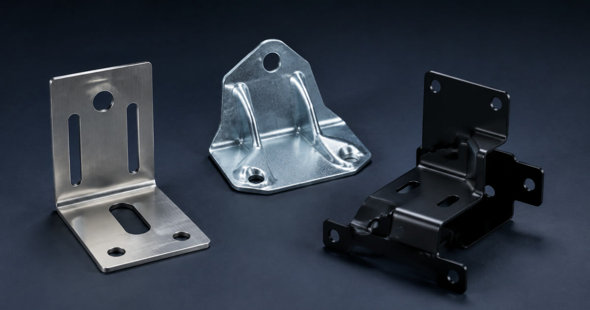
Prepare made-to-print bracket packages with controlled CAD, material, bends, functional datums, hardware, finish and inspection.
Option comparison
Laser cutting and forming usually provide more flexibility for prototypes, lower or variable quantities and design changes. Dedicated stamping can suit stable higher volumes when geometry, tooling cost, ownership, maintenance and expected life are justified. The drawing, tolerances, secondary operations and demand profile determine the actual route.
| Decision factor | Laser-cut and formed | Dedicated stamping |
|---|---|---|
| Best starting point | Prototype, lower or variable batch demand and evolving geometry. | Stable geometry with repeat demand that can justify dedicated tooling. |
| Up-front commitment | Lower dedicated-tool commitment; setup and forming tools may still apply. | Tool design, build, validation, ownership and maintenance must be defined. |
| Change flexibility | Generally easier to revise cutting and forming programs. | Drawing changes can require tool modification or replacement. |
| RFQ basis | Drawing, material, bends, tolerances, secondary operations and batch quantities. | The same inputs plus annual volume, tool life, ownership, storage and change control. |
Selection factors
A 3D model helps communicate shape, but a controlled drawing is still needed to define tolerances, datums, material and acceptance requirements.
| Factor | What to specify |
|---|---|
| Material condition | State the material standard, grade or alloy, temper or condition where relevant and nominal thickness. |
| Geometry and bends | Define datums, critical dimensions, bend radius, angle, direction and any grain-orientation requirement. |
| Features | Call out holes, slots, taps, countersinks, inserts, studs, embosses and their inspection requirements. |
| Edges and appearance | Specify burr limits, edge treatment, cosmetic surfaces, masking and allowable handling marks where important. |
| Finish | Separate base material from plating, coating, passivation, paint or another finish specification. |
| Volume and validation | Provide prototype quantity, production batch, annual volume, tooling assumptions and inspection or first-article needs. |
Practical answer
State who pays for and owns the tool, where it is identified and stored, who maintains and insures it, the quoted tool life and replacement basis, who may authorize modifications, and what happens at transfer or at the end of the program. Put these terms in the quotation and purchase order rather than leaving them to a later tooling invoice.
Basis: TW RFQ editorial guidance, not an external standard.
Application decision
Laser-cut and formed prototypes, turret-punched parts and dedicated stamping tools can serve different stages. Let the drawing and demand profile drive the review.
| Application need | RFQ direction |
|---|---|
| Early fit prototype | Prioritize a flexible low-tooling route and define which dimensions, material and finish may differ from production intent. |
| Low or variable batch demand | Compare flexible cutting and forming routes with setup, nesting, secondary operations and repeatability stated. |
| Stable higher-volume demand | Evaluate dedicated tooling only after annual volume, design stability, tool ownership and maintenance assumptions are clear. |
| Tight formed relationships | Define datums, bend sequence assumptions, material condition and the dimensions to be inspected after forming. |
| Cosmetic exposed part | Mark appearance surfaces, grain or texture direction, edge treatment, masking and allowable handling marks. |
| Part with inserts or welds | Specify exact secondary hardware, orientation, torque or pull criteria, weld callouts and post-process inspection. |
Installed interface
A useful custom-part request keeps design intent, manufacturing notes and acceptance criteria connected to one revision.
Part number, drawing number, revision, units and the controlling file when 2D and 3D differ.
Standard, grade or alloy, temper or condition where relevant and nominal thickness.
Datums, critical dimensions, bend radii, angles, directions, holes, slots and threads.
Inserts, studs, welds, deburr, edge requirements, masking and finishing sequence.
Inspection method, first article, prototype and batch quantities, annual demand and timing.
Typical use
The same hardware family can behave differently across enclosure types. Include the installed context, not only the component name.
Brackets and plates that position electrical, mechanical or control components inside an enclosure.
Formed parts that support hinge, latch, handle or equipment mounting interfaces.
Clips, retainers and mounting parts based on a defined cable, component and enclosure arrangement.
Drawing-based interfaces connecting an enclosure to frames, machines or other assemblies.
Technical boundaries
Use measurable requirements and identify the requested test basis. Product-family names alone do not establish performance or certification.
Buyer questions
Use these answers to prepare a more specific sourcing request.
When annual demand is stable enough to repay the die and the geometry is unlikely to change. Confirm annual volume, part geometry, revision risk and the commercial terms first; until then, laser cutting and press-brake forming keep the design flexible.
Yes. State the prototype quantity, intended process flexibility and later production volume. Prototype and production routes may differ, so approval criteria should be defined in advance.
Do not apply one tight tolerance to every feature. Identify datums and the dimensions that control fit, function or downstream assembly, state their acceptance method, and leave noncritical features under an appropriate general tolerance agreed with the candidate supplier.
They can be evaluated when the exact hardware, location, orientation, installation method, pull or torque requirement and inspection criteria are stated.
Technical reference basis
This category guide supports RFQ preparation. It does not replace an exact supplier drawing, model data, test report, applicable standard or responsible engineering approval.
Official description of a widely used standard for stating and interpreting dimensions and tolerances.
Official index covering drawing types, revision practices, digital product definition and related documentation topics.
Private sourcing review
Have a drawing, photo or reference part?
Send the interface and commercial requirements for a focused Taiwan sourcing review.